
So far in my blogs I utilized Zynq PS DMA and AXI CDMA IPs to move data between DDR RAM, on-chip ram (OCM) and PL Block RAM (BRAM). I have designed Vivado HW and Vitis SW parts and showed latency results for these two scenarios, which you can find at the links all the details:
PS DMA:
AXI CDMA:
These 2 IPs can move data between memory-mapped interfaces on AXI4 protocol. However, there is also another AXI protocol definition in AMBA4 for streaming data in one-way, which is called AXI-Stream interface. AXI-Stream protocol definition is handled in an independent document in ARMs website:
https://developer.arm.com/documentation/ihi0051/b/?lang=en
In the AMBA AXI-Stream Protocol Specification, AXI-Stream protocol is defined as:
“The AXI-Stream protocol is used as a standard interface to exchange data between connected components. AXI-Stream is a point-to-point protocol, connecting a single Transmitter and a single Receiver.”
Signal list for AXI-Stream is much easier and simpler than AXI4 memory-mapped protocol, since in AXI-Stream only one-way data transfer is enabled and there is no addressing. In protocol specification more signals are defined but most common and important ones are:
| Signal | Source | Width | Description |
| ACLK | Clock | 1 | ACLK is a global clock signal. All signals are sampled on the rising edge of ACLK |
| ARESETn | Reset | 1 | ARESETn is a global reset signal. |
| TVALID | Transmitter | 1 | TVALID indicates the Transmitter is driving a valid transfer. A transfer takes place when both TVALID and TREADY are asserted. |
| TREADY | Receiver | 1 | TREADY indicates that a Receiver can accept a transfer |
| TDATA | Transmitter | DWIDTH | TDATA is the primary payload used to provide the data that is passing across the interface. TDATA_WIDTH must be an integer number of bytes and is recommended to be 8, 16, 32, 64, 128, 256, 512 or 1024-bits. |
| TSTRB | Transmitter | DWIDTH/8 | TSTRB is the byte qualifier that indicates whether the content of the associated byte of TDATA is processed as a data byte or a position byte. |
| TKEEP | Transmitter | DWIDTH/8 | TKEEP is the byte qualifier that indicates whether content of the associated byte of TDATA is processed as part of the data Stream. |
| TLAST | Transmitter | 1 | TLAST indicates the boundary of a packet. |
AXI-Stream interface can resemble AXI4 write data channel, which is one of the five AXI4 channels. Here are some differences between AXI-Stream and AXI4 write data channel:
• The AXI write data channel does not permit interleaving.
• The AXI-Stream interface does not have a defined or maximum burst or packet length.
• The AXI-Stream interface allows the data width to be any integer number of data bytes.
• The AXI-Stream interface includes TID and TDEST signals to indicate the source and destination
respectively.
• The AXI-Stream interface defines more precisely the manipulation of the TUSER sideband signals.
• The AXI-Stream interface includes TKEEP signals to allow the insertion and removal of null bytes.
Handshaking in AXI-Stream is very important. There are 3 scenarios defined in the standard:


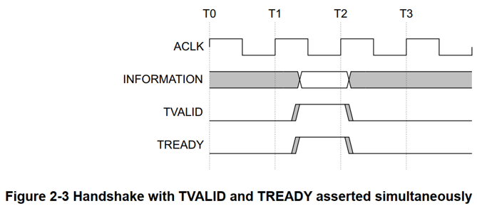
The documentation in the ARM’s website is very clear and there are some details related to byte types and byte qualifiers, which requires the usage of TKEEP and TSTRB signals. I won’t go into details in this post. In most common usages of AXI-Stream data transfers, we usually see TREADY, TVALID, TLAST and TDATA signals only.
In this tutorial, I created an example application in Vivado and Vitis, in which I utilized a loop-back connected Xilinx AXI-Stream FIFO IP and an ILA to monitor AXI-Stream transfers.
Here is the overview of the HW design in Vivado:

I added AXI-Stream FIFO IP to the Vivado IP integrator and keep the default parameter values:

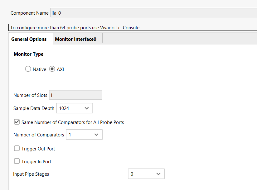
Then I added ILA (integrated logic analyzer) IP to the IP integrator and set the “Monitor Type” parameter to “AXI”:
I just loop-back connected AXI-Stream FIFO streaming tx to the streaming rx and connect these ports to the ILA to monitor AXI-Stream transactions. Also don’t forget to enable PL-PS interrupt in the Zynq PS and connect the interrupt output pin of the AXI-Stream FIFO there. To configure AXI-Stream FIFO registers, an AXI4-Lite slave port is connected to PS through PS general-purpose master ports.
Then I generate the bitstream. You can regenerate the block design with tcl scripts that I provided in my github page:
https://github.com/mbaykenar/zynq-soc-hw-sw-design/blob/main/ders16/axi_stream_fifo.tcl
https://github.com/mbaykenar/zynq-soc-hw-sw-design/blob/main/ders16/system.tcl
After generation of bitstream, I exported the design to Vitis for SW design. In Vitis, I just opened AXI-Stream FIFO IP’s example interrupt design from the Vitis setup folder:

Let’s analyze the example SW:
2 arrays are created for buffering source and destination data:
u32 SourceBuffer[MAX_DATA_BUFFER_SIZE * WORD_SIZE];
u32 DestinationBuffer[MAX_DATA_BUFFER_SIZE * WORD_SIZE];
Interrupt controller and AXI-Stream FIFO peripheral instances are created:
/*
 * Device instance definitions
 */
XLlFifo FifoInstance;

/*
 * Instance of the Interrupt Controller
 */
static INTC Intc;
In the main function, first AXI-Stream FIFO IP is initialized through the instance:
	/* Initialize the Device Configuration Interface driver */
	Config = XLlFfio_LookupConfig(DeviceId);
	if (!Config) {
		xil_printf("No config found for %d\r\n", DeviceId);
		return XST_FAILURE;
	}

	/*
	 * This is where the virtual address would be used, this example
	 * uses physical address.
	 */
	Status = XLlFifo_CfgInitialize(InstancePtr, Config, Config->BaseAddress);
	if (Status != XST_SUCCESS) {
		xil_printf("Initialization failed\n\r");
		return Status;
	}
Then ISR (interrupt status register) is resetted and checked:
	/* Check for the Reset value */
	Status = XLlFifo_Status(InstancePtr);
	XLlFifo_IntClear(InstancePtr,0xffffffff);
	Status = XLlFifo_Status(InstancePtr);
	if(Status != 0x0) {
		xil_printf("\n ERROR : Reset value of ISR0 : 0x%x\t"
			    "Expected : 0x0\n\r",
			    XLlFifo_Status(InstancePtr));
		return XST_FAILURE;
	}
Here AXI4-Lite transactions are occurred, but we can’t see them in the ILA, since we only connected AXI-Stream ports of the FIFO IP. Then interrupt controller is configured:
	/*
	 * Connect the Axi Streaming FIFO to the interrupt subsystem such
	 * that interrupts can occur. This function is application specific.
	 */
	Status = SetupInterruptSystem(&Intc, InstancePtr, FIFO_INTR_ID);
	if (Status != XST_SUCCESS) {
		xil_printf("Failed intr setup\r\n");
		return XST_FAILURE;
	}

	XLlFifo_IntEnable(InstancePtr, XLLF_INT_ALL_MASK);
Finally data is transferred from transmitter port to receiver port through loop-back connection. Now we should see AXI-Stream data transfers in the ILA. But, we need to set some condition for ILA trigger. I will talk about it after analyzing the SW.
	Done = 0;
	/* Transmit the Data Stream */
	Status = TxSend(InstancePtr, SourceBuffer);
	if (Status != XST_SUCCESS){
		xil_printf("Transmission of Data failed\n\r");
		return XST_FAILURE;
	}
	while(!Done);
Transmitted and received data are compared to check if any error occurs:
	/* Compare the data sent with the data received */
	xil_printf("Comparing data...\n\r");
	for( i=0 ; i<MAX_DATA_BUFFER_SIZE ; i++ ){
		if ( *(SourceBuffer + i) != *(DestinationBuffer + i) ){
			err = 1;
			break;
		}

	}
Okey, now it is time to test this setup in the Zedboard. First I opened Vivado HW Manager and see our Zynq SoC:

Then in Vitis IDE, I created a debug configuration and simply press debug button:

After the initialization of Zynq registers, especially the PLL registers, clock will be running since in our design we utilized for PL peripherals the clock from the PS. Now we are able to see our Zynq PL is programmed and ILA started to run:

I created a trigger condition for the ILA as:

In this trigger condition, the ILA will wait till a rising from 0 to 1 occurs in TVALID signal, which is the control signal for AXI-Stream transmitter port stating that the AXI data is valid. Then I run the trigger in the ILA screen and ILA state changes from IDLE to Waiting for Trigger:

I debug the SW until TxSend function, where FIFO transfer will occur and ILA is still waiting TVALID to goes high. After I run the SW, we see the trigger condition is satisfied and the waveform is saved in the ILA:

When we zoom into the trigger condition time, we see that at each clock cycle AXI DATA is incremented till the latest transfer, where TLAST goes high and TVALID goes low:


Then we run the SW till the end of the main function and got no error, which means our AXI-Stream FIFO works as expected.
I also added the C code to github repo, but again this is just Xilinx’s example code:
https://github.com/mbaykenar/zynq-soc-hw-sw-design/blob/main/ders16/helloworld.c
In this post, I talked about what is AXI-Stream protocol, created and run a simple tutorial to show AXI-Stream transfers in AXI-Stream FIFO IP through ILA. A Vivado HW design and then Vitis SW design is shown as a tutorial, also necessary files can be found in my github repo:
https://github.com/mbaykenar/zynq-soc-hw-sw-design/tree/main/ders16
Regards,
Mehmet Burak AYKENAR
You can connect me via LinkedIn: Just sent me an invitation