
In my latest post, I talked about AXI-Stream protocol and showed a running design on Zedboard utilizing AXI-Stream FIFO and ILA:
Today, I will show how to create a custom AXI-Stream peripheral in Vivado with VHDL. The use case is an arithmetic co-processor, where the arithmetic operation of the co-processor will be selected between addition, subtraction, multiplication via an AXI4-Lite slave interface. There will be an AXI-Stream slave interface, which sinks data coming from an AXI-Stream master interface, then the arithmetic operation for the incoming data will be performed according to AXI4-Lite registers and the result will be streamed-out through an AXI-Stream master interface. To validate this IP, I will create a Vivado project, in which an AXI-Stream FIFO IP will be utilized to source and sink AXI-Stream data packets in another day of course.
By the way if you want to learn more about AXI-Stream protocol, you can check the specification document in ARMs website:
https://developer.arm.com/documentation/ihi0051/b/?lang=en
Let’s define the I/O ports of the custom IP:
AXI-Stream receiver port
| clk, rstn | in |
| tvalid | in |
| tdata (64) | in |
| tlast | in |
| tready | out |
AXI-Stream transmitter port
| clk, rstn | in |
| tvalid | out |
| tdata (64) | out |
| tlast | out |
| tready | in |
These are the minimum required AXI-Stream ports in order to connect our custom IP to AXI-Stream FIFO IP:

In order to create custom AXI IP, Vivado has a great wizard named as “Create and Package New IP”:
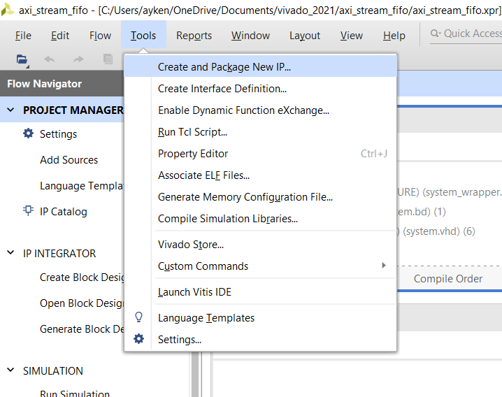
When you click this tab the wizard window opens:

In the next window we choose “Create a new AXI4 peripheral” selection:

In the next page we give peripheral details. I created a new folder for packing my all custom Ips and create a sub-folder for this IP:

In the next page we define AXI interfaces. I added a master AXI-Stream interface for transmitting data and a slave AXI-Stream interface for receiving data. I wanted to change data width from 32 to 64 but could’t do it. I will change data width in the VHDL file by hand in this case since I need 64-bit data, where 2 numbers can be received and processed in the same AXI clock cycle. I also add an AXI4-Lite slave interface to control arithmetic operation.

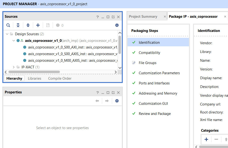
When we finish the IP wizard, it opens a new Vivado project to edit the IP. Here we can edit and repack the IP. The most important part is of course adding our functionality to RTL code.
The functionality of the coprocessor will be derived from these requirements:
– AXI4-Lite transactions shall be handled. Only the first register (reg0) can be modified by the master. The value of the reg0 will be outputted to the top module of the coprocessor.
– In the top module, based on reg0 of the AXI4-lite interface module, addition, subtraction or multiplication operation will be performed on the incoming AXI-Stream packets.
– The output of the performed arithmetic function will be transmitted in the master AXI-Stream interface at the next clock.
In Vivado, when you use custom AXI IP wizard with an AXI-Stream slave and a master interface, and an AXI4-Lite interface, it creates a top module instantiating 3 sub-modules, two for AXI-Stream and one for AXI4-Lite interfaces. For AXI4-Lite interface, the template code creates 4 registers and handles AXI4 transactions. We can use this template, with just small modifications we can output the value of reg0 from this template code in the module. For AXI-Stream interfaces, the template code infers a FIFO and pushes incoming data in slave interface or sent data in the master interface. I don’t want to use this template, so I just removed out all data but I/O ports and parameters in the top file. I also removed tstrobe ports and changed AXI data width from 32 to 64. I will write from scratch all the code.
Module ports consist of an AXI4-Lite slave, an AXI-Stream master and an AXI-Stream slave:
-- Ports of Axi Slave Bus Interface S00_AXI
s00_axi_aclk	: in std_logic;
s00_axi_aresetn	: in std_logic;
s00_axi_awaddr	: in std_logic_vector(C_S00_AXI_ADDR_WIDTH-1 downto 0);
s00_axi_awprot	: in std_logic_vector(2 downto 0);
s00_axi_awvalid	: in std_logic;
s00_axi_awready	: out std_logic;
s00_axi_wdata	: in std_logic_vector(C_S00_AXI_DATA_WIDTH-1 downto 0);
s00_axi_wstrb	: in std_logic_vector((C_S00_AXI_DATA_WIDTH/8)-1 downto 0);
s00_axi_wvalid	: in std_logic;
s00_axi_wready	: out std_logic;
s00_axi_bresp	: out std_logic_vector(1 downto 0);
s00_axi_bvalid	: out std_logic;
s00_axi_bready	: in std_logic;
s00_axi_araddr	: in std_logic_vector(C_S00_AXI_ADDR_WIDTH-1 downto 0);
s00_axi_arprot	: in std_logic_vector(2 downto 0);
s00_axi_arvalid	: in std_logic;
s00_axi_arready	: out std_logic;
s00_axi_rdata	: out std_logic_vector(C_S00_AXI_DATA_WIDTH-1 downto 0);
s00_axi_rresp	: out std_logic_vector(1 downto 0);
s00_axi_rvalid	: out std_logic;
s00_axi_rready	: in std_logic;

-- Ports of Axi Slave Bus Interface S00_AXIS
s00_axis_aclk	: in std_logic;
s00_axis_aresetn: in std_logic;
s00_axis_tready	: out std_logic;
s00_axis_tdata	: in std_logic_vector(C_S00_AXIS_TDATA_WIDTH-1 downto 0);
s00_axis_tlast	: in std_logic;
s00_axis_tvalid	: in std_logic;

-- Ports of Axi Master Bus Interface M00_AXIS
m00_axis_aclk	: in std_logic;
m00_axis_aresetn: in std_logic;
m00_axis_tvalid	: out std_logic;
m00_axis_tdata	: out std_logic_vector(C_M00_AXIS_TDATA_WIDTH-1 downto 0);
m00_axis_tlast	: out std_logic;
m00_axis_tready	: in std_logic
There is one component, axis_coprocessor_v1_0_S00_AXI, which handles AXI4-Lite transactions and gives the output port “operation”:
-- component declaration
component axis_coprocessor_v1_0_S00_AXI is
generic (
C_S_AXI_DATA_WIDTH	: integer	:= 32;
C_S_AXI_ADDR_WIDTH	: integer	:= 4
);
port (
-- MBA START
operation	: out std_logic_vector(1 downto 0);
-- MBA END
S_AXI_ACLK	: in std_logic;
S_AXI_ARESETN	: in std_logic;
S_AXI_AWADDR	: in std_logic_vector(C_S_AXI_ADDR_WIDTH-1 downto 0);
S_AXI_AWPROT	: in std_logic_vector(2 downto 0);
S_AXI_AWVALID	: in std_logic;
S_AXI_AWREADY	: out std_logic;
S_AXI_WDATA	: in std_logic_vector(C_S_AXI_DATA_WIDTH-1 downto 0);
S_AXI_WSTRB	: in std_logic_vector((C_S_AXI_DATA_WIDTH/8)-1 downto 0);
S_AXI_WVALID	: in std_logic;
S_AXI_WREADY	: out std_logic;
S_AXI_BRESP	: out std_logic_vector(1 downto 0);
S_AXI_BVALID	: out std_logic;
S_AXI_BREADY	: in std_logic;
S_AXI_ARADDR	: in std_logic_vector(C_S_AXI_ADDR_WIDTH-1 downto 0);
S_AXI_ARPROT	: in std_logic_vector(2 downto 0);
S_AXI_ARVALID	: in std_logic;
S_AXI_ARREADY	: out std_logic;
S_AXI_RDATA	: out std_logic_vector(C_S_AXI_DATA_WIDTH-1 downto 0);
S_AXI_RRESP	: out std_logic_vector(1 downto 0);
S_AXI_RVALID	: out std_logic;
S_AXI_RREADY	: in std_logic
);
end component axis_coprocessor_v1_0_S00_AXI;
I calculated 3 arithmetic operations in parallel combinational logic and muxed the results with operation is the select signal. I sign-extended addition and subtraction results:
--==========================================================================
-- Combinational assignments
--==========================================================================
result 	<= 	add_result when operation = "00" else
			sub_result when operation = "01" else
			mul_result when operation = "10" else
			add_result;

add_result(31 downto 0)                 <= 	s00_axis_tdata(8*8-1 downto 4*8) + s00_axis_tdata(4*8-1 downto 0*8);
add_result(8*8-1 downto 4*8) 	        <= (others => (add_result(31)));
sub_result(31 downto 0) 		<= 	s00_axis_tdata(8*8-1 downto 4*8) - s00_axis_tdata(4*8-1 downto 0*8);
sub_result(8*8-1 downto 4*8) 	        <= (others => (sub_result(31)));
mul_result 				<= s00_axis_tdata(8*8-1 downto 4*8) * s00_axis_tdata(4*8-1 downto 0*8);
The tready signal of the AXI-Stream slave interface is following tready of the AXI-Stream master input signal, since we don’t need a kind of buffer and monitor if buffer is full or not. So, if the receiver module is ready to receive data from our coprocessor IP, our IP is ready to get data from the transmitter side:
--==========================================================================
-- TREADY is always '1' if the receiver is ready
--==========================================================================
P_TREADY : process (s00_axis_aclk)
begin
if rising_edge(s00_axis_aclk) then
	if s00_axis_aresetn = '0' then
		s00_axis_tready	<= '0';
	elsif (m00_axis_tready = '1') then
		s00_axis_tready	<= '1';
	else
		s00_axis_tready	<= '0';
	end if;
end if;
end process P_TREADY;
tlast signal of the master port also follows tlast of the slave port:
--==========================================================================
-- Master TLAST follows slave TLAST
--==========================================================================
P_TLAST : process (s00_axis_aclk)
begin
if rising_edge(s00_axis_aclk) then
	if s00_axis_aresetn = '0' then
		m00_axis_tlast	<= '0';
	elsif (s00_axis_tlast = '1') then
		m00_axis_tlast	<= '1';
	else
		m00_axis_tlast	<= '0';
	end if;
end if;
end process P_TLAST;
tvalid of the master port also follows tvalid of the receiver port, but I also added the condition of tready of the master port:
--==========================================================================
-- Master TVALID follows slave TVALID
--==========================================================================
P_TVALID : process (s00_axis_aclk)
begin
if rising_edge(s00_axis_aclk) then
	if s00_axis_aresetn = '0' then
		m00_axis_tvalid	<= '0';
	elsif (s00_axis_tvalid = '1'and m00_axis_tready = '1') then
		m00_axis_tvalid	<= '1';
	else
		m00_axis_tvalid	<= '0';
	end if;
end if;
end process P_TVALID;
Master tdata is connected to result signal and registered:
--==========================================================================
-- Master TDATA is assigned to result with clock
--==========================================================================
P_TDATA : process (s00_axis_aclk)
begin
if rising_edge(s00_axis_aclk) then
if s00_axis_aresetn = '0' then
m00_axis_tdata <= (others => '0');
else
m00_axis_tdata <= result;
end if;
end if;
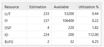
end process P_TDATA;The resource utilization after synthesis:
By the way, in the past I did custom AXI4-Lite and AXI4-Full IP designs but did not post implementation details like this writing. But, you can find RTL codes for these custom IPs below in the links to my github page:
https://github.com/mbaykenar/zynq-soc-hw-sw-design/tree/main/ders6
https://github.com/mbaykenar/zynq-soc-hw-sw-design/tree/main/ders9
Ok I hear some voices we wrote the RTL but did not verify the core yet. I will verify this custom AXI-Stream IP in the next post using UVVM library.
In this post, I showed how to create an AXI-Stream custom IP in Vivado. I defined a co-processor with the ability of doing addition, subtraction and multiplication. You can find VHDL code in my github repo:
https://github.com/mbaykenar/zynq-soc-hw-sw-design/tree/main/ders17
Regards,
Mehmet Burak AYKENAR
You can connect me via LinkedIn: Just sent me an invitation