
Digital design is a hot topic, it was, and it will be in near future according to some surveys if you google it. If you want to be a digital design engineer or if you are now and want to see job opportunities, you will see different job descriptions. One difference is, if you are aiming ASIC or FPGA as an end product. Digital design part of ASIC is usually called as front-end design and physical implementation is usually as back-end design. In most cases, front-end ASIC design and FPGA design is very similar, I am not saying “same”, of course there are different aspects in ASIC design comparing to the FPGA design but main concepts are “similar”. Some job descriptions say “digital design IC engineer” and specifies the needs more clearly, but in most descriptions you understand if the end product is ASIC or FPGA.
Then there is “verification”. Some job descriptions named as “digital design verification engineer”, “digital verification engineer”, “digital design engineer – verification & validation” etc. Most companies make a distinction between “design” and “verification”. Well there are companies where the designers are also the verifiers. Some companies couldn’t find necessary budget to seperate design and verification units and hire less engineers, so the result is the designer needs to verify its own design! This scheme is not desirable if you are working on an avionics system. There are standards and recommendations about the project cycle and quality assurance. DO-254 is one of the most important standards, or recommendations as it is called, that must be obeyed. DO-254 compliance suggest that the teams for designing and verifying the digital system should be different. Even, if it is possible they should be in different buildings, rooms etc.
Well, there are reasons behind this suggestions. I am lucky, or maybe unlucky as I am working as a digital design engineer and I also verify my designs myself. The lucky part is I also learn verification, and simulation techniques of digital design, which is not a bad thing. Unlucky part is, expertising on both design and verification is not an easy task. Especially formal verification is very different from the waveform viewing or basic testbench simulations. There are methodologies about verification and nowadays the most famous one is UVM – Universal Verification Methodology. There were different methodologies from different vendors or groups before, but now at the end of 2021, UVM and so SystemVerilog (SV) language is the de facto standard for verification community.
SystemVerilog is based on Verilog HDL. Well there are 2 HDL (Hardware Description Language) now mostly used: Verilog/SystemVerilog and VHDL. According to surveys Verilog seems to be used slightly more by the community but this is the overall usage of the language, I mean both design and verification. Verilog is in 29th rank and VHDL is in 32nd according to IEEE spectrum (data is from 24.11.2021):

When it comes to the design, well I don’t want to say VHDL is used more but what I experience, see, hear and read is VHDL is more used for design as now (IMO). I am also a VHDL user for digital design. So, after I finished my design, should I use UVM and SystemVerilog for verification or simulations? According to my experience, learning Verilog as an HDL language is not so difficult if you know VHDL or visa versa. However, SystemVerilog with UVM methodology is not that easy.
The question is do I have any other options regarding verification methodology with VHDL language rather than SV and UVM? The answer is yes. There are two highly-used libraries, or methodologies written in VHDL for verification purposes: OSVVM (Open Source VHDL Verification Methodology) and UVVM (Universal VHDL Verification Methodology). Here are the links for these two:
Mr. Jim Lewis is the head of OSVVM developers and Mr. Espen Tallaksen is the head of UVVM developers (I am not sure about “head of developer” but they post on LinledIn regularly about their methodologies). I want to try both methods and want to do a comparison post later. Now I am on learning phase. I will start with UVVM. Therefore, I went through UVVM github page and look for which simulation tools support UVVM.
Well in UVVM github page below is written:
UVVM is tool and library independent, but it must be compiled with VHDL 2008. UVVM has been tested with the following simulators:
Modelsim version 19.1
Riviera-PRO version: 2018.10.137.7135
Questa Sim version 19.1
GHDL version 0.36
Note Questa Sim version 19.2 and Modelsim version 19.2 have known bugs that might prevent UVVM from working properly.
Python is required if you want to execute the VVC generation scripts.
Vivado simulator is not listed. I asked Espen in a webinar if Vivado supports UVVM and he replied UVVM is based on VHLD-2008 functions and attributes. Vivado does not support full of VHDL-2008 [by the way it was a webinar sponsored by Siements 🙂 As a Xilinx FPGA and Vivado user, I was not happy with the answer and looked for other simulator options. At first I tried GHDL, which is an open-source free VHDL simulator. Here is the link for GHDL github page:
I failed compiling UVVM on GHDL. To be frank, I did not spent too much time, but I can say I tried my best. I also did not want to go for open-source tool for formal verification because getting help from community is usually not so speedy, and finding tutorials, video examples, posts etc. is also not an easy task for GHDL. Then I decided to go for Modelsim/Questasim, as it seems it is the most used tool for verification engineers. There is also Aldec Riviera that I heard a lot, but basic animal instinct, follow the herd prevailed :l
I knew Siemens bought Mentor, so I went Siements webpage to find if any free version of Questa or Modelsim. Well at that time (24.11.2021) there was no information or download page from Siemens. Then I looked at Intel’s webpage (Intel bought Altera FPGA company). Intel offers free version of Quartus and Modelsim. I selected 19.1 release (as UVVM is tested on 19.1 version) and lite edition which is free:

And below I only downloaded ModelSim, because I don’t need Quartus, which is needed to synthesis and implementation of Intel FPGAs.

Then I finished installation. You can open ModelSim and create projects, add sources and do simulations. But, if you use Vivado, you can also open ModelSim from Vivado and simulate your design without explicitly opening ModelSim and creating project. Here is the way:
First I opened a Vivado project. I used the project which is about integer division in my first blog post:
https://www.mehmetburakaykenar.com/integer-division-in-fpgas-with-vhdl-approach/87/
Here is the design module:
library IEEE;
use IEEE.STD_LOGIC_1164.ALL;
use IEEE.STD_LOGIC_ARITH.ALL;
use IEEE.STD_LOGIC_UNSIGNED.ALL;

entity divide_by_number is
port (
clk         : in std_logic;
dividend    : in STD_LOGIC_VECTOR (7 downto 0);
divisor     : in STD_LOGIC_VECTOR (7 downto 0);
quotient    : out STD_LOGIC_VECTOR (7 downto 0)
);
end divide_by_number;

architecture Behavioral of divide_by_number is

component div_gen_0 IS
PORT (
aclk                    : IN STD_LOGIC;
s_axis_divisor_tvalid   : IN STD_LOGIC;
s_axis_divisor_tdata    : IN STD_LOGIC_VECTOR(7 DOWNTO 0);
s_axis_dividend_tvalid  : IN STD_LOGIC;
s_axis_dividend_tdata   : IN STD_LOGIC_VECTOR(7 DOWNTO 0);
m_axis_dout_tvalid      : OUT STD_LOGIC;
m_axis_dout_tuser       : OUT STD_LOGIC_VECTOR(0 DOWNTO 0);
m_axis_dout_tdata       : OUT STD_LOGIC_VECTOR(15 DOWNTO 0)
);
END component;

signal tvalid           : std_logic := '0';
signal div_by_zero      : std_logic_vector (0 downto 0) := (others => '0');
signal result           : STD_LOGIC_VECTOR(15 DOWNTO 0) := (others => '0');

begin

div_ip : div_gen_0
PORT MAP (
aclk                    => clk,
s_axis_divisor_tvalid   => '1',
s_axis_divisor_tdata    => divisor,
s_axis_dividend_tvalid  => '1',
s_axis_dividend_tdata   => dividend,
m_axis_dout_tvalid      => tvalid,
m_axis_dout_tuser       => div_by_zero,
m_axis_dout_tdata       => result
);

quotient    <= result(15 downto 8);

end Behavioral;
Here is a simple testbench code testing a few cases:
library IEEE;
use IEEE.STD_LOGIC_1164.ALL;
use IEEE.STD_LOGIC_ARITH.ALL;
use IEEE.STD_LOGIC_UNSIGNED.ALL;

entity tb_divide_by_number is
end tb_divide_by_number;

architecture Behavioral of tb_divide_by_number is

component divide_by_number is
port (
clk         : in std_logic;
dividend    : in STD_LOGIC_VECTOR (7 downto 0);
divisor     : in STD_LOGIC_VECTOR (7 downto 0);
quotient    : out STD_LOGIC_VECTOR (7 downto 0)
);
end component;

signal clk          : std_logic := '0';
signal dividend     : STD_LOGIC_VECTOR (7 downto 0) := (0 => '1', others => '0');
signal divisor      : STD_LOGIC_VECTOR (7 downto 0) := (0 => '1', others => '0');
signal quotient     : STD_LOGIC_VECTOR (7 downto 0);

begin

DUT : divide_by_number
port map (
clk         => clk          ,
dividend    => dividend     ,
divisor     => divisor      ,
quotient    => quotient
);

process begin
clk <= '0';
wait for 5 ns;
clk <= '1';
wait for 5 ns;
end process;

process begin

wait for 100 ns;
wait until falling_edge(clk);

dividend    <= CONV_STD_LOGIC_VECTOR(15,8);
divisor     <= CONV_STD_LOGIC_VECTOR(5,8);

wait for 10 ns;

dividend    <= CONV_STD_LOGIC_VECTOR(15,8);
divisor     <= CONV_STD_LOGIC_VECTOR(4,8);

wait for 10 ns;

dividend    <= CONV_STD_LOGIC_VECTOR(15,8);
divisor     <= CONV_STD_LOGIC_VECTOR(3,8);

wait for 10 ns;

dividend    <= CONV_STD_LOGIC_VECTOR(15,8);
divisor     <= CONV_STD_LOGIC_VECTOR(2,8);

wait for 10 ns;

dividend    <= CONV_STD_LOGIC_VECTOR(15,8);
divisor     <= CONV_STD_LOGIC_VECTOR(1,8);

wait for 10 ns;

dividend    <= CONV_STD_LOGIC_VECTOR(15,8);
divisor     <= CONV_STD_LOGIC_VECTOR(0,8);

wait for 20 ns;

assert false
report "SIM DONE"
severity failure;

end process;

end Behavioral;
I went to the simulation settings, this is the default form:

Then I changed Target Simulator to ModelSim and Vivado gave the following warning:

Then I go Tools -> Compile Simulation Libraries

Because compilation of libraries for all device familes may take long time, I only choose Artix7, Spartan7 and Zynq-7000 which I mostly use:

I changed the compiled library location to a folder that I created inside modelsim installation path.

Well compiling took about 5 minutes on my laptop. Well the result was an empty folder 😊 I assume this is due to administrative permission issues on modelsim setup location. So I choose another folder which is a “normal” folder and recompile the libraries. This time it takes 40-50 minutes to compile the libraries. Well if you won’t use Xilinx IPs then you don’t need to compile these libraries but I used divide IP in my design so I need to compile. By the way the folder size is about 4 GB !!!

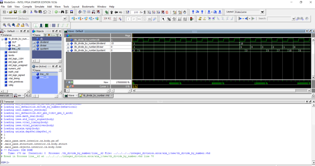
Then after I press the “Run Simulation” button on Vivado, Modelsim opened and the simulation run:
So this is the end of the tutorial. On the next post, I want to compile UVVM libraries for Modelsim and show a simple example. First, I want to start with UVVM-light repo, which only includes util and bfm libraries. I will use a UART transmitter module as design and try to verify it with UVVM uart bfm package.
Regards,
Mehmet Burak AYKENAR
You can connect me via LinledIn: Just sent me an invitation
Hi Burak abi,
First of all, thank you for sharing. It’s great to see you posting about verification topics rather than design. Its difficult to find thorough examples on verification methodologies. That’s because tools used for verification are the paid ones, not a topic that is covered in undergrad curriculum mostly, number of people specifically working in this field is relatively low. Nevertheless we can find decent resources, books, tutorials etc.
I wonder that how much time did writing take when compared to doing the actual work 🙂 Because I am planning to write and share articles someday. Btw, I’ve been looking for a free simulator that I can download, install easily and do some verification work, implement robust testing etc.
Good to see there are VHDL alternatives but I am not a VHDL person 🙂 Sometimes I thought about why people really digging hard to do verification with VHDL because SystemVerilog promises strong features(Idk what’s the current status with VHDL libraries, does it support writing temporal logic like SVA?) considering verification(and design) and it’s not too hard indeed but definetely requires extra work. Unfortunately there is no free tool to use that fully complies SV/UVM although there is for Verilog(icarus verilog). But I don’t feel Verilog is a really good option after SystemVerilog and I don’t want to invest on it.
On the simulator side I thought I can consider using Modelsim since it supports SV/UVM partially. Currently Siemens/Mentor is not distributing it due to some US export issues and Quartus SE says its limited to 10k lines of code. Thus I will be looking for other solutions. First candidate is the Verilator :). I guess it’s not gonna be serious SV work but SystemC or C++. Let’s see how it goes.
A good example in terms of statistics of verification frameworks based on github repositories, https://larsasplund.github.io/github-facts/index.html
Hi Emin,
It is a very delayed comment 🙂 but I think cocotb is nowadays gaining so much usage in the verification field. I looked at VUnit github repo and cocotb. As now (22 Oct 2022), VUnit github repo has 561 stars, while cocotb 1.2K stars. VUnit has 56 contributors, while cocotb has 112.
UVVM/OSVVM are VHDL based. UVVM has 264 stars, OSVVM 179 stars.
Also, verification engineers are more software-centric engineers than hardware-centric engineers. The popularity of python is huge, so I assume that cocotb will have more usage to it in future
This link may be useful:
https://www.adiuvoengineering.com/post/microzed-chronicles-ghdl-and-uvvm-framework
What you wrote is very helpful to me. Do you know how to use modelsim to simulate the vivado project with xilinx IP used independently?